STIR 2.4 HP
History
Description
The STIR 2.4 HP (Signal Tracking and Illumination Radar, High Power) is a medium-to-long-range fire control radar manufactured by Thales Group. It has a 2.4-meter I-band cassegrain antenna and an electro-optical camera with black & white and infrared modes for target observation and identification. It can provide fire control for guns and illumination for semi-active radar-homing missiles, including the ESSM and SM-2 missile families. It has an instrumented range of 512 kilometers, though typical acquisition and tracking range against a missile-sized target would be between 100 and 150 kilometers. Total mass of the director is 2200 kilograms, average power of the transmitter is 5 KW.
In addition to the director, each STIR 2.4 HP mounting requires the following internal systems, not drawn:
- Supply and amplifier cabinet: 6px w x 13px h x 5px d, 590 kg
- TWT radar cabinet: 8px w x 13px h x 6px d, 1120 kg
- Track processing cabinet: 5px w x 11px h x 3px d, 159 kg
- Frequency control cabinet: 5px w x 12px h x 3px d, 200 kg
- Waveguide driver: 4px h x 5px h x 4px d, 83 kg
Used on
Part description
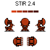
The upper row has an aft-facing side view, a side-facing side view, and a fore-facing side view. The row below has an aft-facing top view and a forward-facing top view.
All views assume that the light source always comes from the top and right side of the canvas. If your shading rule differs, especially when shading the front view and top view of a ship, you may have to alter the shading.
All views employ a five-tone shading palette with light-to-shadow transitions at approximately 45 degrees, as recommended by the style guide. If you use a different number of shades, you may want to consider altering the part.
The part consists of a stabilized pedestal, which is fixed in place, and a director mount, which traverses. The black line running across the base separates the two, except for the pyramid-shaped protrusion on the side of the base under the dome, which is attached to the stabilized pedestal, not to the traversing mount. If you wish to draw a front- or rear-facing pedestal with the antenna pointing toward the viewer, please appropriately combine the antenna and arm assembly from the front view with the pedestal from the aft- or fore-facing side view.
Real photos indicate that the railing-like structure on the rear of the mount is present on all STIR 2.4 HP directors installed on ships, even if it is omitted by some blueprints. If high-resolution reference photos indicate that this railing structure is absent on the ship you are drawing, you may omit it.
On some ships, this railing is painted black; on others, it is painted in the same gray as the rest of the part. Some installations also appear to paint the radome white. The entire part uses a uniform "primer" shading palette, so pick paint colors per section to suit the ship you are drawing.
